Laptop & Tablet Parts
 Desktop & All-in-one Parts
 Dell Server Parts


In this Dell laptop tutorial we are going to show you how to install and replace the Bottom Base Chassis on your Latitude E5420 laptop. These installation instructions have be made into 36 easy to follow printable steps. We have also create a video tutorial that shows you how to install your Latitude E5420 Bottom Base Chassis.
Before you begin
 Please take the time read the following safety guidelines when working on static sensitive electrical components.
Dell repair manual service precautions
Tools needed for this laptop repair
- 1 x small phillips head screwdriver
- 1 x small plastic scribe
Latitude E5420 Bottom Base Chassis
Latitude E5420 Bottom Base Chassis
|
Eligible for $5.00 Economy Shipping. Only 13 left in stock - order soon. 
Eligible for $5.00 1st Class Shipping. In Stock 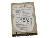
Eligible for $5.00 1st Class Shipping. Only 0 left in stock - order soon. DIY Discount - Parts-People.com offers 5% off to all DO-IT-YOURSELFERS!
Use this coupon code to save 5% off these parts DIYM514
|
Video tutorial repair manual
Installation and Removal Instructions
Latitude E5420 Bottom Base Chassis
Step 1
- Slide the latches over to unlock the battery.

Step 2
- Lift the battery out of the laptop.
Step 3
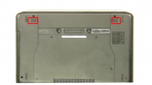
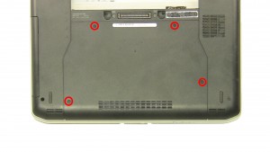
- Remove the screws.
- Slide the door down and remove the door.
Step 4
- Remove the screw.
- Slide the optical drive out of the laptop.
Step 5
- Remove the hard drive screws.
- Using the pull tab, lift the hard drive out of the laptop.
Step 6
- Unplug the antenna cables.
- Remove the screw.
Step 7
- Remove the wireless card.
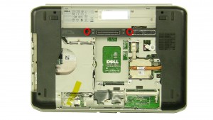
Step 8
- Remove the bottom keyboard screws.
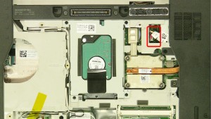
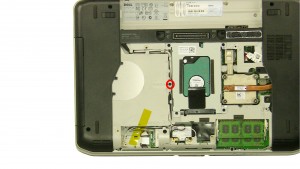
Step 9
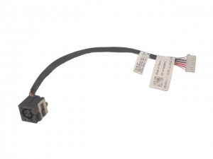
- Unplug the DC jack cable.
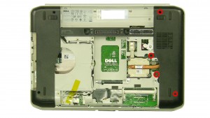
Step 10
- Remove the screws.
- Remove the CPU door.
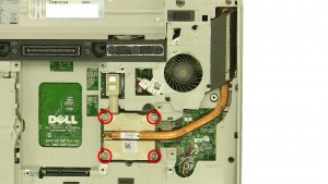
Step 11
- Loosen the heatsink screws.
- Remove & clean the heatsink.
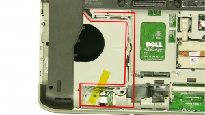
Step 12
- Loosen the wireless antenna cables.
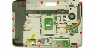
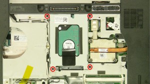
Step 13
- Remove the bottom palmrest screws.
- Turn the laptop over and open it up.
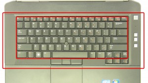
Step 14
- Carefully pry up and unsnap the keyboard bezel.
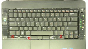
Step 15
- Remove the keyboard screws.
- Carefully lift the keyboard up.
Step 16
- Unplug the keyboard cable.
- Remove the keyboard.
Step 17
- Remove the palmrest screws.
- Unplug the palmrest cables.
Step 18
- Unsnap & remove the palmrest starting on the left or right side.
Step 19
- Remove the screw.
- Unplug the cable.
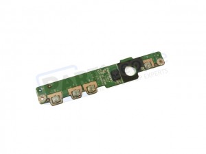
Step 20
- Remove the LED circuit board.
Step 21
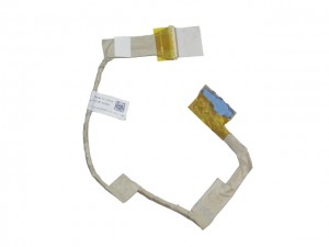
- Pull the antenna cables through the base.
- Loosen the plastic.
- Unplug & loosen the LCD cables.
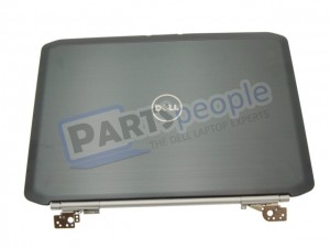
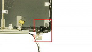
Step 22
- Remove the left hinge screws.
- Remove the right hinge screws.
- Remove the display assembly.
Step 23
- Remove the screws.
- Remove the left support bracket.
Step 24
- Remove the screws.
- Remove the right support bracket.
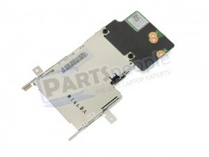
Step 25
- Remove the screws.
- Remove the express card reader.
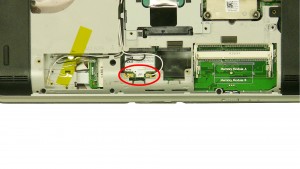
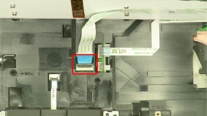
Step 26
- Unplug the bluetooth cable.
- Remove the screw.
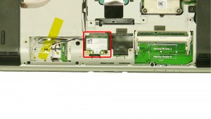
Step 27
- Remove the bluetooth card.
Step 28
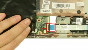
- Unplug the cables.
- Remove the screw.
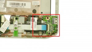
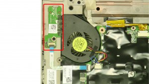
Step 29
- Remove the circuit board.
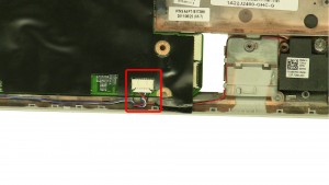
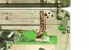
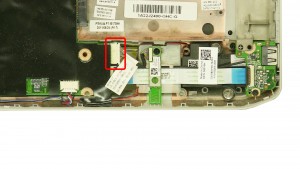
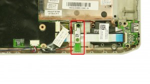
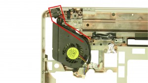
Step 30
- Unplug the speaker cable.
- Unplug the fan cable.
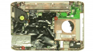
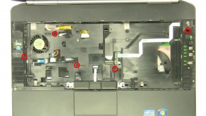
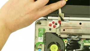
Step 31
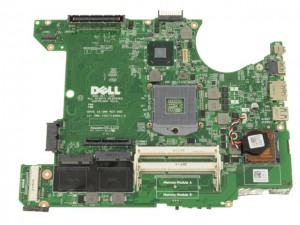
- Remove the motherboard screws.
- Remove the motherboard.
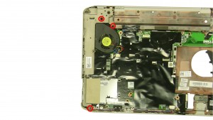
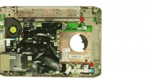
Step 32
- Remove the DC jack.
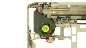
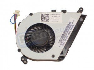
Step 33
- Remove the screws.
- Remove the cooling fan.
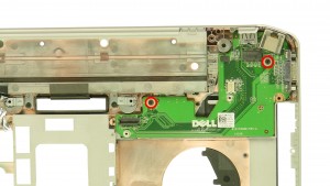
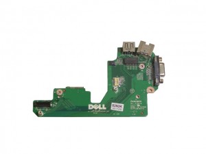
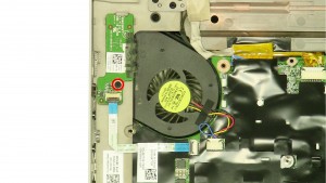
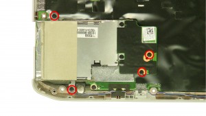
Step 34
- Remove the screws.
- Remove the circuit board.
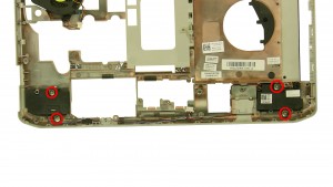
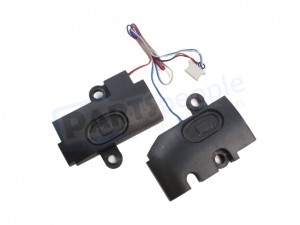
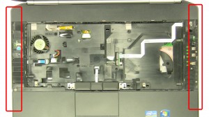
Step 35
- Remove the speaker screws.
- Remove the speakers.
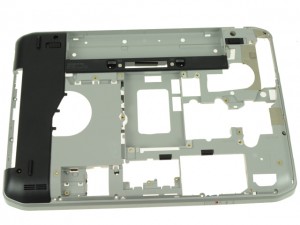
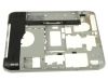
Step 36
- The remaining piece is the bottom base chassis.
Latitude E5420 Bottom Base Chassis
Latitude E5420 Bottom Base Chassis
|
|
Eligible for $5.00 Economy Shipping. Only 13 left in stock - order soon.
Eligible for $5.00 1st Class Shipping. In Stock
Eligible for $5.00 1st Class Shipping. Only 0 left in stock - order soon. DIY Discount - Parts-People.com offers 5% off to all DO-IT-YOURSELFERS!
Use this coupon code to save 5% off these parts DIYM514
|