Laptop & Tablet Parts
 Desktop & All-in-one Parts
 Dell Server Parts


In this Dell laptop tutorial we are going to show you how to install and replace the Palmrest Touchpad on your Inspiron 15-7548 (P41F-001) laptop. These installation instructions have be made into 17 easy to follow printable steps. We have also create a video tutorial that shows you how to install your Inspiron 15-7548 (P41F-001) Palmrest Touchpad.
Before you begin
 Please take the time read the following safety guidelines when working on static sensitive electrical components.
Dell repair manual service precautions
Tools needed for this laptop repair
- 1 x small phillips head screwdriver
- 1 x small plastic scribe
Inspiron 7548 Palmrest Touchpad
Inspiron 15 7548 Palmrest Touchpad
|
Eligible for $5.00 Economy Shipping. Only 19 left in stock - order soon. 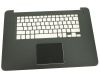
Eligible for $5.00 Economy Shipping. In Stock 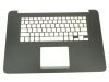
Eligible for $5.00 Economy Shipping. Only 3 left in stock - order soon. DIY Discount - Parts-People.com offers 5% off to all DO-IT-YOURSELFERS!
Use this coupon code to save 5% off these parts DIYM514
|
Video tutorial repair manual
Installation and Removal Instructions
Inspiron 15-7548 (P41F-001) Palmrest Touchpad
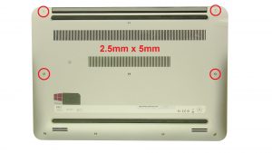
Step 1
- Loosen the top screws (6 x M2.5 x 5mm).
- Loosen the captive screws (cannot be removed).
- Remove the access door.
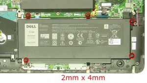
Step 2
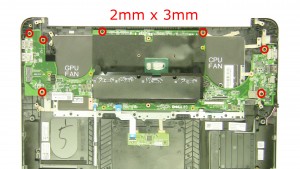
- Remove the battery screws (5 x M2 x 4mm).
- Lift the battery & turn it over.
- Unplug & remove the battery cable.
- Remove the battery.
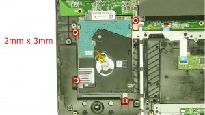
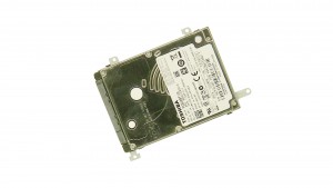
Step 3
- Remove the hard drive screws (4 x M2 x 3mm).
- Slide the hard drive down and remove it from the laptop.
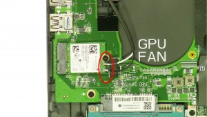
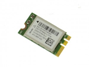
Step 4
- Unplug & loosen the antenna cables.
- Remove the screw (1 x M2 x 3mm).
- Remove the wireless card.
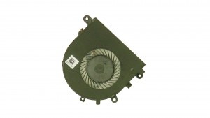
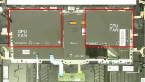
Step 5
- Loosen the plastic.
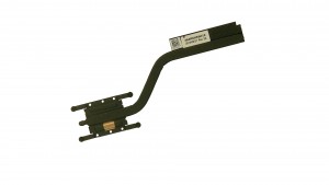
- Loosen the heatsink screws (cannot be removed).
- Remove & clean the heatsink.
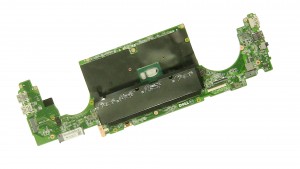
Step 6
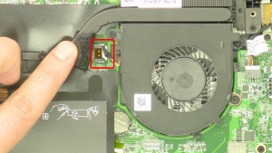
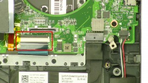
- Unplug the LCD cable.
- Loosen the LCD cable.
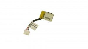
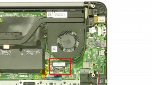
Step 8
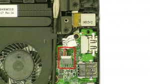
- Unplug the DC jack.
- Remove the DC jack.
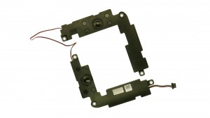
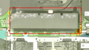
Step 9
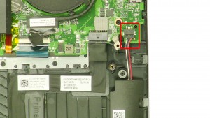
- Unplug the speaker cable.
- Remove the speakers.
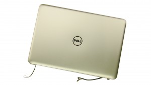
Step 10
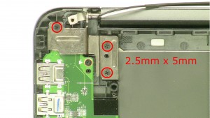
- Remove the left hinge screws.
- Remove the right hinge screws.
- Remove the display assembly.
Step 11
- Unplug the keyboard cable.
- Unplug the keyboard backlight cable.
Step 12
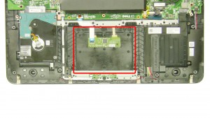
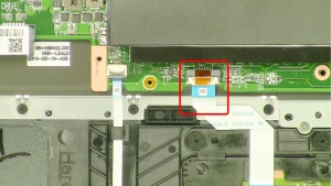
- Unplug the touchpad cable.
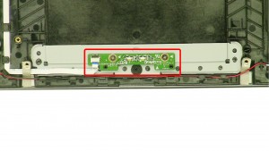
- Unplug the LED circuit board cable.
Step 14
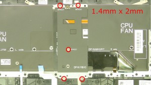
- Remove the keyboard bracket screws (5 x M1.4mmx2mm).
- Remove the keyboard bracket.
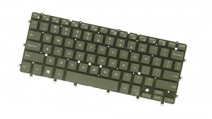
Step 15
- Remove the plastic covers.
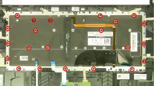
Step 16
- Remove the keyboard screws.
- Remove the keyboard.
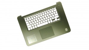
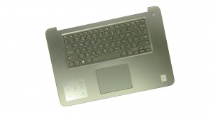
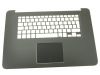
Step 17
- The remaining piece is the palmrest touchpad.
Inspiron 7548 Palmrest Touchpad
Inspiron 15 7548 Palmrest Touchpad
|
|
Eligible for $5.00 Economy Shipping. Only 19 left in stock - order soon.
Eligible for $5.00 Economy Shipping. In Stock
Eligible for $5.00 Economy Shipping. Only 3 left in stock - order soon. DIY Discount - Parts-People.com offers 5% off to all DO-IT-YOURSELFERS!
Use this coupon code to save 5% off these parts DIYM514
|