Laptop & Tablet Parts
 Desktop & All-in-one Parts
 Dell Server Parts


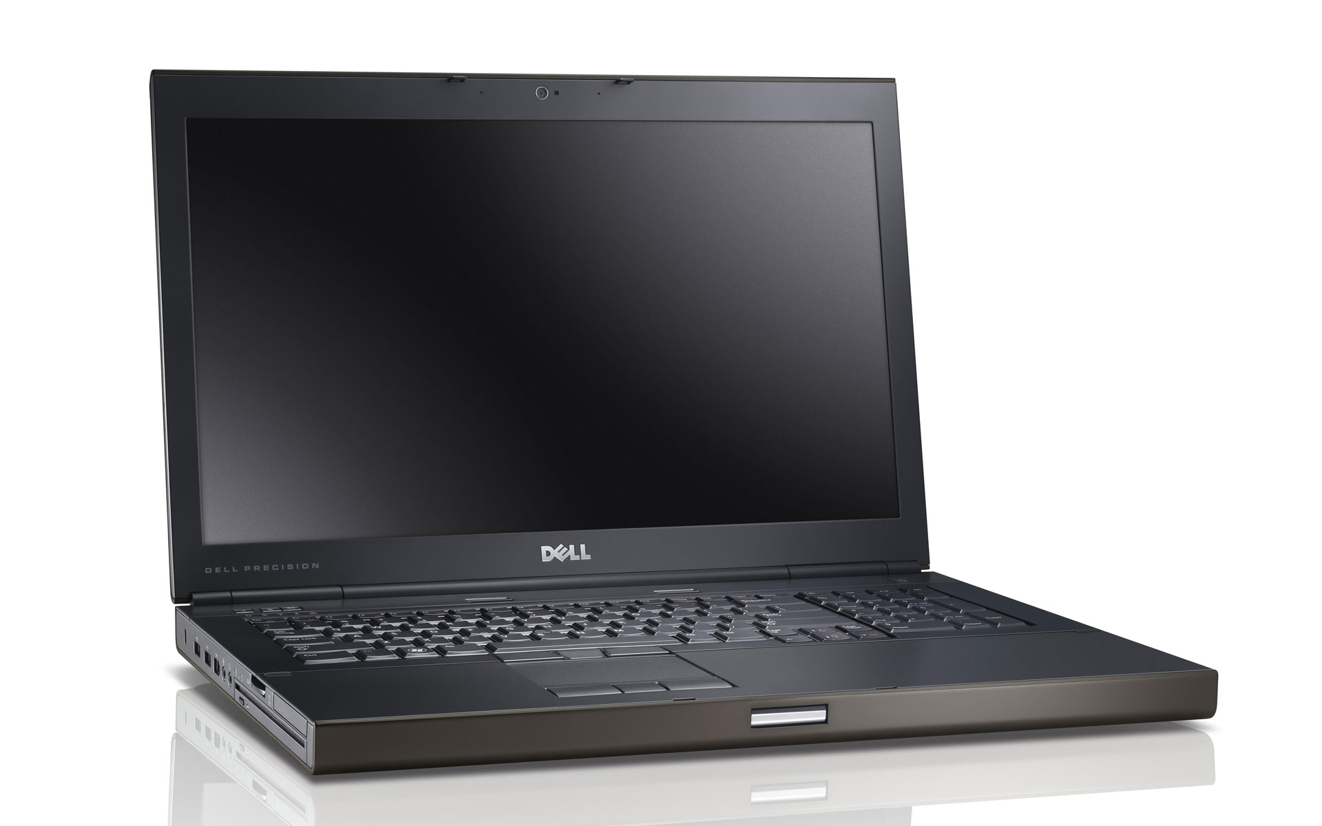
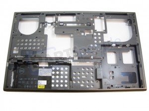
In this Dell laptop tutorial we are going to show you how to install and replace the Motherboard on your Precision M6600 laptop. These installation instructions have be made into 32 easy to follow printable steps. We have also create a video tutorial that shows you how to install your Precision M6600 Motherboard.
Before you begin
 Please take the time read the following safety guidelines when working on static sensitive electrical components.
Dell repair manual service precautions
Tools needed for this laptop repair
- 1 x small phillips head screwdriver
- 1 x small plastic scribe
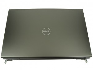
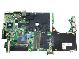
Precision M6600 Motherboard
Precision M6600 Motherboard
|
Eligible for $5.00 Economy Shipping. In Stock 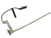
Eligible for $5.00 1st Class Shipping. In Stock 
Eligible for $5.00 1st Class Shipping. In Stock DIY Discount - Parts-People.com offers 5% off to all DO-IT-YOURSELFERS!
Use this coupon code to save 5% off these parts DIYM514
|
Video tutorial repair manual
Installation and Removal Instructions
Precision M6600 Motherboard
Step 2
- Press the card in to eject it.
- Remove the SD card.
Step 5
- Remove the 4 - M3 x 5mm primary hard drive screws.
- Remove the 1 - M2 x 3mm primary hard drive latch screw.
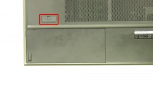
- Slide the latch down to eject the primary Hard Drive.
Step 6
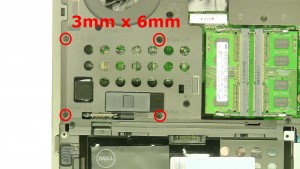
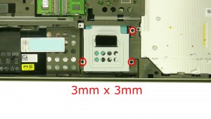
- Remove the 3 - M3 x 3mm secondary hard drive screws.
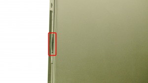
- Slide the secondary Hard Drive down & lift it out of the laptop.
Step 11
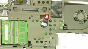
- Unplug & remove the CMOS battery.
Step 14
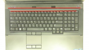
- Turn the laptop over & open it up.
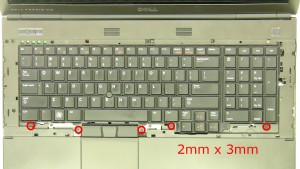
- Carefully unsnap the Keyboard Bezel starting at the top of the keyboard.
Step 17
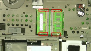
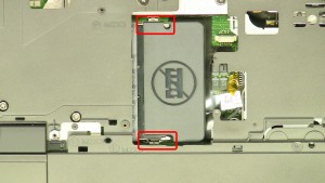
- If you have a memory blank, separate the clips & lift it out of the laptop.
- If you do not have a memory blank, skip this step.
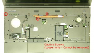
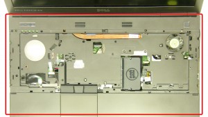
Step 19
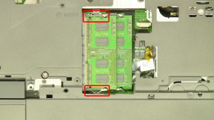
- Loosen the 3 captive screws.(These will not be fully removed.)
- Remove the 11 - M2 x 3mm palmrest screws.
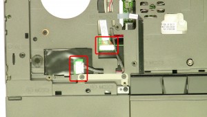
Step 20
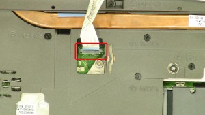
- Unplug the speaker & volume control cable.
- Unplug the touchpad cable.
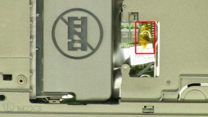
Step 21
- Unplug the bluetooth cable.
- Unplug the power button cable.
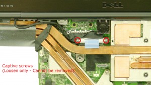
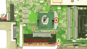
Step 23
- Loosen the screws.
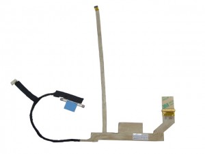
- Unplug & loosen the display cables.
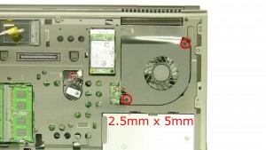
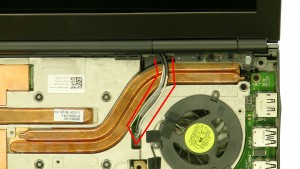
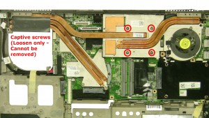
- Loosen the heatsink screws.
- Remove the Heatsink.
Step 25
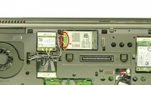
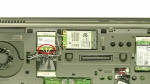
- Pull the antenna cables through the motherboard.
- Unplug the fan cable.
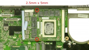
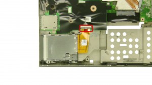
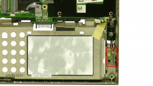
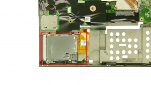
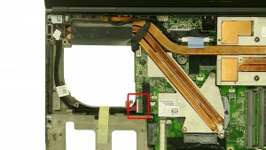
Step 28
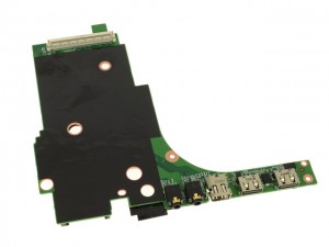
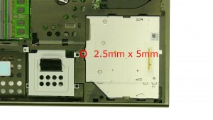
- Unplug the express cable.
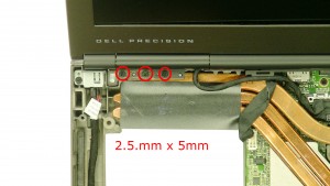
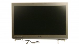
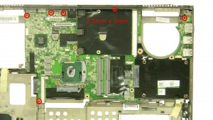
Step 30
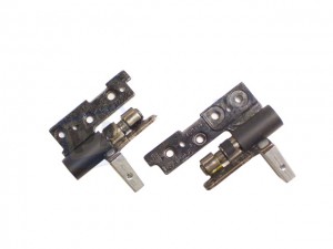
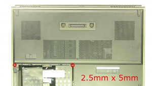
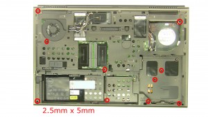
- Remove the 3 - M2.5 x 5mm left hinge screws.
- Remove the 3 - M2.5 x 5mm right hinge screws.
- Remove the Display Assembly from the base.
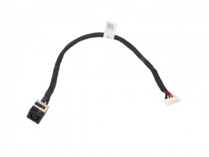
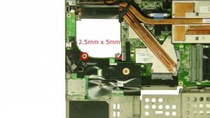
Step 31
- Unplug the DC jack cable.
- Unplug the WiFi catcher switch.
Precision M6600 Motherboard
Precision M6600 Motherboard
|
|
Eligible for $5.00 Economy Shipping. In Stock
Eligible for $5.00 1st Class Shipping. In Stock
Eligible for $5.00 1st Class Shipping. In Stock DIY Discount - Parts-People.com offers 5% off to all DO-IT-YOURSELFERS!
Use this coupon code to save 5% off these parts DIYM514
|