Laptop & Tablet Parts
 Desktop & All-in-one Parts
 Dell Server Parts


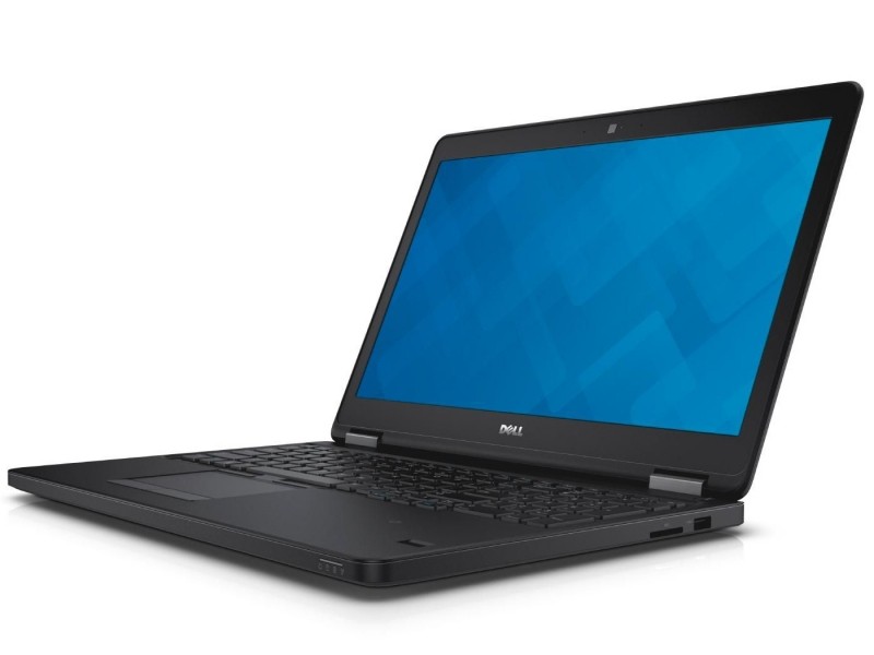
In this Dell laptop tutorial we are going to show you how to install and replace the Motherboard on your Latitude E7450 laptop. These installation instructions have be made into 24 easy to follow printable steps. We have also create a video tutorial that shows you how to install your Latitude E7450 Motherboard.
Before you begin
 Please take the time read the following safety guidelines when working on static sensitive electrical components.
Dell repair manual service precautions
Tools needed for this laptop repair
- 1 x small phillips head screwdriver
- 1 x small plastic scribe
Latitude E7450 Motherboard
Latitude E7450 Motherboard
|
Eligible for $5.00 1st Class Shipping. In Stock 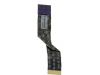
Eligible for $5.00 1st Class Shipping. In Stock 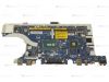
$79.95
Dell Latitude E7450 Motherboard System Board with i5 2.2GHz with Nvidia Graphics - No USH - 796WF Eligible for FREE Economy Shipping. Only 6 left in stock - order soon. DIY Discount - Parts-People.com offers 5% off to all DO-IT-YOURSELFERS!
Use this coupon code to save 5% off these parts DIYM514
|
Video tutorial repair manual
Installation and Removal Instructions
Latitude E7450 Motherboard
Step 3
- Unplug the hard drive cable.
- Remove the 3 - M2.5 x 5mm hard drive caddy screws.
- Remove the hard drive.
Step 8
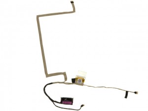
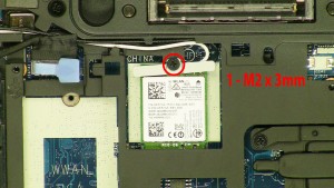
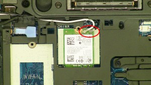
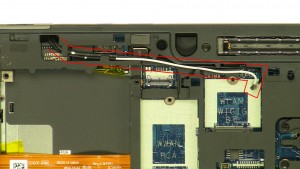
- Loosen the antenna cables.
Step 11
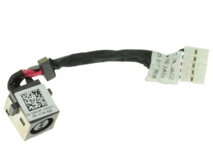
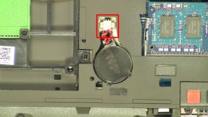
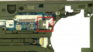
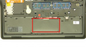
- Unplug the DC jack cable.
Step 12
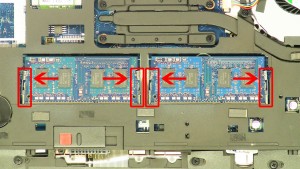
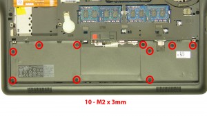
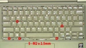
- Remove the 10 - M2 x 3mm screws under the battery.
- Remove the 6 - M2.5 x 5mm screws under the access door.
Step 13
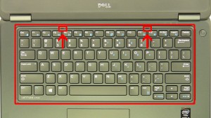
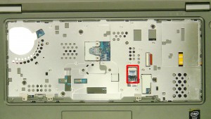
- Loosen the plastic keyboard cable cover.
- Unplug the keyboard cable.
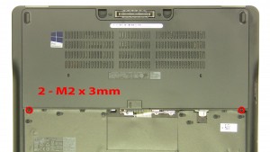
Step 14
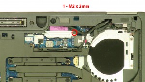
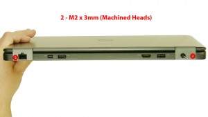
- Remove the 2 - M2 x 3mm back hinge cover screws.
- Open the laptop.
Step 15
- Using a plastic scribe or small flat head screwdriver, carefully pry up the Keyboard Bezel & remove it from the laptop.
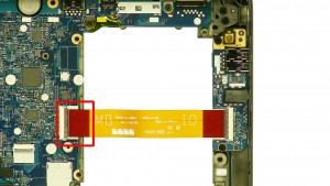
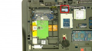
Step 19
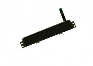
- Unplug the power button circuit board cable.
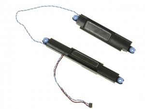
- Unplug the speaker cable.
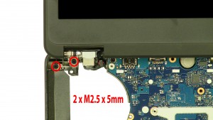
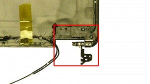
Step 21
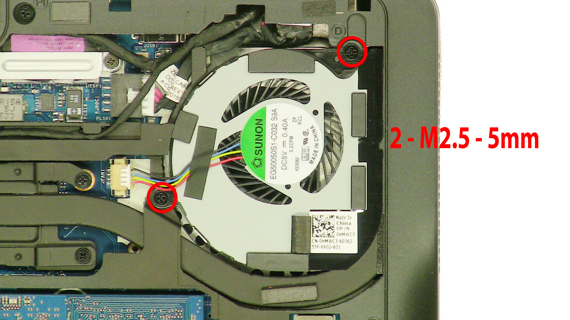
- Remove the 2 - M2.5 x 5mm left hinge screws.
- Remove the 2 - M2.5 x 5mm right hinge screws.
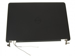
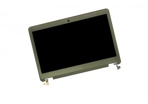
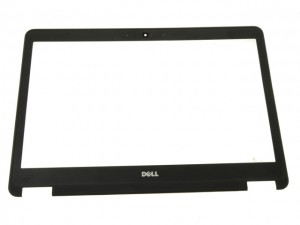
- Remove the LCD Display Assembly.
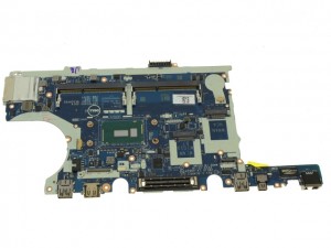
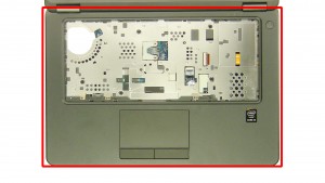
Step 24
- The remaining piece is the Motherboard.
Latitude E7450 Motherboard
Latitude E7450 Motherboard
|
|
Eligible for $5.00 1st Class Shipping. In Stock
Eligible for $5.00 1st Class Shipping. In Stock
$79.95
Dell Latitude E7450 Motherboard System Board with i5 2.2GHz with Nvidia Graphics - No USH - 796WF Eligible for FREE Economy Shipping. Only 6 left in stock - order soon. DIY Discount - Parts-People.com offers 5% off to all DO-IT-YOURSELFERS!
Use this coupon code to save 5% off these parts DIYM514
|