Laptop & Tablet Parts
 Desktop & All-in-one Parts
 Dell Server Parts


In this Dell laptop tutorial we are going to show you how to install and replace the DC Jack on your Latitude 13-7350 (P58G-001) laptop. These installation instructions have be made into 5 easy to follow printable steps. We have also create a video tutorial that shows you how to install your Latitude 13-7350 (P58G-001) DC Jack.
Before you begin
 Please take the time read the following safety guidelines when working on static sensitive electrical components.
Dell repair manual service precautions
Tools needed for this laptop repair
- 1 x small phillips head screwdriver
- 1 x small plastic scribe
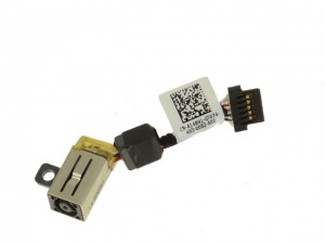
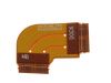
Latitude 7350 DC Jack
Latitude 13 7350 DC Jack
|
Eligible for $5.00 1st Class Shipping. In Stock 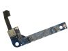
Eligible for $5.00 1st Class Shipping. Only 1 left in stock - order soon. 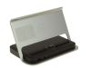
Eligible for $5.00 Economy Shipping. Only 1 left in stock - order soon. DIY Discount - Parts-People.com offers 5% off to all DO-IT-YOURSELFERS!
Use this coupon code to save 5% off these parts DIYM514
|
Video tutorial repair manual
Installation and Removal Instructions
Latitude 13-7350 (P58G-001) DC Jack
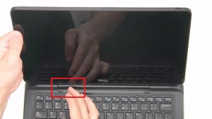
Step 1
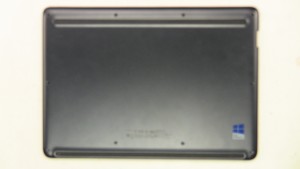
- Slide button to the left to unlock tablet from base.
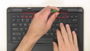
Step 2
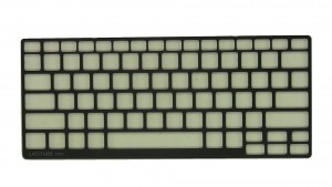
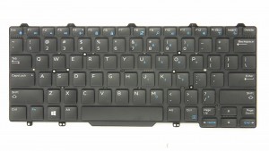
- Use flat head screwdriver to pry open and remove Keyboard Bezel.
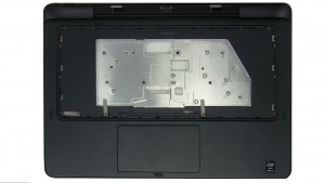
- Unscrew palmrest and keyboard screws (4 x M2 x 3mm).
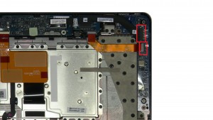
Step 4
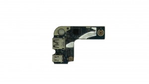
- Unplug and remove cables.
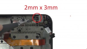
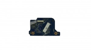
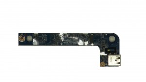
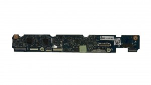
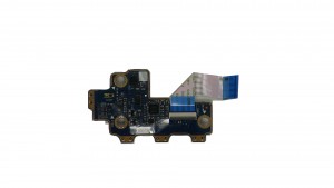
- Unscrew and remove USB Circuit Board (2 x M2 x 3mm).
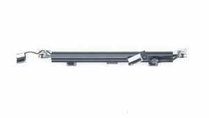
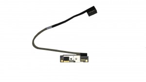
- Unplug DC Jack cable.