Laptop & Tablet Parts
 Desktop & All-in-one Parts
 Dell Server Parts


In this Dell laptop tutorial we are going to show you how to install and replace the Palmrest Touchpad on your Latitude E7470 (P61G001) laptop. These installation instructions have be made into 23 easy to follow printable steps. We have also create a video tutorial that shows you how to install your Latitude E7470 (P61G001) Palmrest Touchpad.
Before you begin
 Please take the time read the following safety guidelines when working on static sensitive electrical components.
Dell repair manual service precautions
Tools needed for this laptop repair
- 1 x small phillips head screwdriver
- 1 x small plastic scribe
Latitude E7470 Palmrest Touchpad
Latitude E7470 Palmrest Touchpad
|
Eligible for $5.00 Economy Shipping. Only 2 left in stock - order soon. 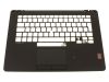
Eligible for $5.00 Economy Shipping. Only 3 left in stock - order soon. 
Eligible for $5.00 Economy Shipping. In Stock DIY Discount - Parts-People.com offers 5% off to all DO-IT-YOURSELFERS!
Use this coupon code to save 5% off these parts DIYM514
|
Video tutorial repair manual
Installation and Removal Instructions
Latitude E7470 (P61G001) Palmrest Touchpad
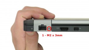
Step 2
- Remove the 2 - M2 x 3mm left & right hinge cover screws.
- Remove the left & right Hinge Covers.
Step 4
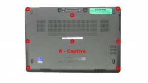
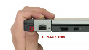
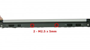
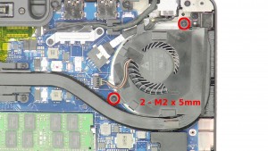
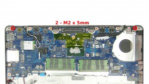
- Remove the 2 - M2.5 x 5mm back edge dock frame screws.
- Remove the 4 - M2 x 5mm bottom dock frame screws.
- Remove the Dock Frame.

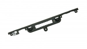
Step 8
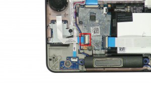
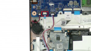
- Unplug the smart card cable.
- Unplug the mouse button cable.
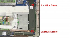
Step 9
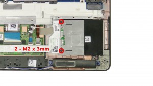
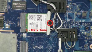
- Remove the 1 - M2 x 3mm screw.
- Loosen the screw.
- Remove the bracket.
- Remove the M.2 Solid State Drive.
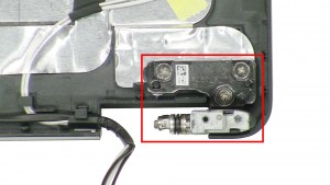
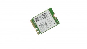
Step 14
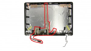
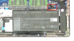
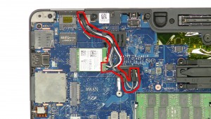
- Unplug & loosen the antenna cables.
Step 16
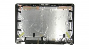
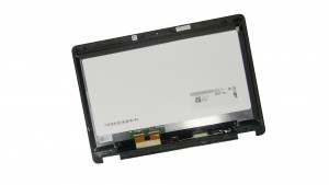
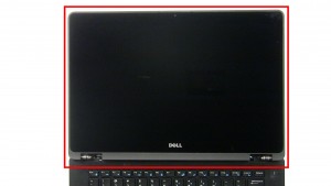
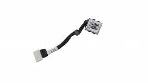
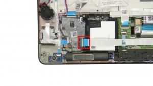
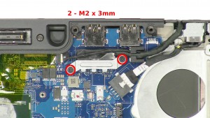
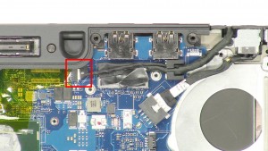
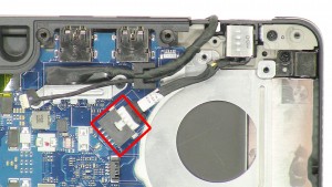
- Unplug the touchscreen cable.
- Unplug & loosen the LCD cable.

Step 20
Step 22
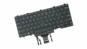
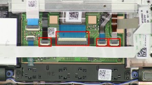
- Unplug the keyboard cables.
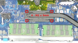
- Remove the 17 - M2 x 3mm keyboard bracket screws.
- Lift the keyboard & bracket out of the palmrest.
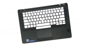
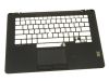
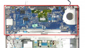
Step 23
- The remaining piece is the Palmrest Touchpad.
Latitude E7470 Palmrest Touchpad
Latitude E7470 Palmrest Touchpad
|
|
Eligible for $5.00 Economy Shipping. Only 2 left in stock - order soon.
Eligible for $5.00 Economy Shipping. Only 3 left in stock - order soon.
Eligible for $5.00 Economy Shipping. In Stock DIY Discount - Parts-People.com offers 5% off to all DO-IT-YOURSELFERS!
Use this coupon code to save 5% off these parts DIYM514
|